Column design
Cross-sectional Inputs
All references to EN 1995-1-1:2004 unless otherwise stated.
This a column of constant cross-section under combined bending and compression parallel to the grain, taking into account buckling effects, according to Clause 6.3.2.

Timber Type
The Timber Type of the cross-section. See the timber database section for the types supported by Teretron.
Column length l
The length of the column, in mm.
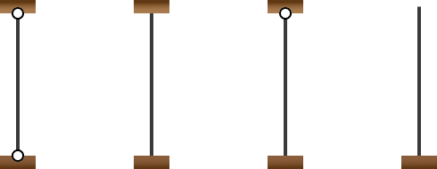
Support conditions
The type of support conditions. Teretron supports the following support conditions for columns:
- ○ Pinned-pinned (pinned on both supports)
- ○ Fully fixed (fully fixed on both supports)
- ○ Fixed-pinned (one support fully fixed, and the other pinned)
- ○ Fixed-free (one support fully fixed, and the other free to rotate and move in all directions)

For other support conditions, the user has to select other and enter the relevant effective length factor.
Note that you can change the effective length factors used by Teretron for either the specific column or the entire project via Component > Component Factors or Project > Project Factors respectively.
Factor lef / l
This refers to the effective length factor for support conditions not covered by Teretron (choice "Other" in the "Support Conditions" list box).

Cross-section type
The geometry type of the cross-section.
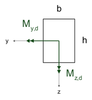
Width bThe width of a rectangular cross-section, in mm. Depth hThe depth of a rectangular cross-section, in mm. |

|
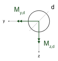
Diameter dThe diameter of a circular cross-section, in mm. |

|
Area A
The area of a generic cross-section, in mm2.
Second moment of area Iyy
The second moment of area of a generic cross-section about the y-y axis, in mm4.
Section modulus Wy
The section modulus of the cross-section about the y-y axis, in mm3.
Second moment of area Izz
The second moment of area of a generic cross-section about the z-z axis, in mm4.
Section modulus Wz
The section modulus of the cross-section about the z-z axis, in mm3.

Area reduction
The area reduction ΔA refers to reductions in the nominal cross-section size that have to be taken into account in the calculation of the member strength (e.g. holes from fasteners) according to Subclause 5.2(2).
It should be given as a percentage of the total nominal area of the cross-section.
Section modulus reduction
The section modulus reduction ΔW refers to reductions in the nominal cross-sectional modulus that are to be taken into account in the calculation of the member strength (e.g. holes from fasteners) according to Subclause 5.2(2).
It should be given as a percentage of the total nominal section modulus of the cross-section.

Characteristic modulus of elasticity Em.0.05
The characteristic modulus of elasticity in bending parallel to the plane of the board, in GPa.
It is required for certain types of plywood, where the existing standards do not provide a value.
Characteristic modulus of elasticity Em.90.05
The characteristic modulus of elasticity in bending perpendicular to the plane of the board, in GPa.
It is required for certain types of plywood, where the existing standards do not provide a value.
Factor βc
The straightness factor βc.
It is required for plywood where no value is given in the Eurocodes standard.

Contribution of cross-section size on the determination of member strength properties
Includes factors kh for the calculation of the member strength in solid timber, glulam and LVL, according to Clauses 3.2, 3.3, and 3.4.
In the case of an LVL member under tension, the member length is also required.
Contribution of the load distribution system in the member strength properties
Includes factor ksys for the calculation of the member strength, according to Clause 6.6, for a member that functions as part of a continuous load distribution system.
Note that Subclause 6.6(3) states that the strength verification for a continuous load distribution system should be carried out assuming short-term load duration.
